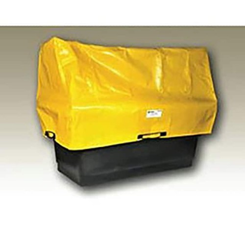

Integrating the Enpac Spill Containment Cover FO (SKU: 5275-TARP) into an electronic system requires a fundamental shift in thinking, as this component is not a conventional electronic part but a physical containment and protective barrier. Its primary circuit topology is best understood as a mechanical isolation and environmental shield rather than an electrical circuit. The recommended “topology” is to place the cover directly over the equipment or spill-prone area, ensuring it forms a continuous, impermeable layer. Design best practices involve treating the cover as a sacrificial element in the overall system architecture: it must be the outermost layer, positioned to intercept any liquid or debris before it reaches sensitive electronics. For electrical safety, never route power or signal lines through the cover itself; instead, ensure all cables enter the protected zone from below or through sealed gaskets. The cover should be considered a zero-impedance mechanical ground plane in terms of physical protection, but it offers no electrical conductivity—it is a non-conductive tarp designed for chemical resistance, not current carrying.
Component selection for supporting passives in this context refers to the mechanical and environmental interfaces around the cover. For sealing and securing the cover to a chassis or enclosure, select stainless steel or chemically resistant plastic fasteners (e.g., nylon or PTFE) to avoid corrosion from potential spills. Gaskets or compression seals should be made of fluoroelastomer (Viton) or EPDM rubber, as these materials are compatible with the wide range of chemicals the Enpac cover is designed to contain. For any pass-through connectors or cable glands, choose IP68-rated options with appropriate chemical resistance. Do not use standard PVC or silicone grommets, as they may degrade upon contact with solvents or acids. The cover itself is made from a proprietary polyurethane-coated fabric; ensure that all supporting brackets or frames are constructed from corrosion-resistant alloys like 316 stainless steel or coated aluminum to prevent galvanic reactions in wet or corrosive environments.
PCB layout recommendations must consider the cover’s role as a physical barrier. Place all PCBs and sensitive components inside a sealed enclosure that is then covered by the Enpac tarp—never mount PCBs directly under the tarp without a secondary housing. The layout of the PCBA should follow standard best practices for the application (e.g., low-ESR capacitors near power pins, short traces for high-speed signals), but with an added emphasis on conformal coating. After assembly, apply a robust conformal coating (acrylic or parylene) to the entire PCB to provide a secondary moisture barrier. For routing tips, ensure that any external wiring entering the protected zone is routed downward to allow gravity to drain liquids away from entry points. Avoid routing cables across the top of the enclosure; instead, bring them in from the bottom or side through sealed glands. The cover’s footprint should extend at least 2-3 inches beyond the edges of the enclosed equipment to prevent splash ingress from oblique angles.
EMC/EMI considerations are unique because the Enpac cover is non-conductive and provides no electromagnetic shielding. It will not attenuate radiated emissions or susceptibility. Therefore, the system’s EMI protection must come entirely from the internal enclosure and PCB design. Use a conductive metal chassis or shield can inside the cover to contain radiated noise. If the application is in a high-EMI environment, consider adding a conductive gasket between the internal enclosure lid and base. The cover itself can actually be a benefit for ESD mitigation—since it is non-conductive, it prevents direct discharge paths to the enclosure, but it can also accumulate static charge. To mitigate this, ensure the internal enclosure is well-grounded and that the cover is not allowed to rub against sensitive components. For mitigation strategies, use a static-dissipative additive in the internal enclosure paint or add a bleed resistor to ground from the chassis. Never rely on the tarp for any EMC function; treat it as a purely mechanical safeguard.
Common design pitfalls include assuming the cover provides electrical insulation or grounding—it does not. Never use the tarp as a circuit board substrate or as a standoff. Another pitfall is inadequate sealing around penetrations: if cables or pipes pass through the cover, they must be sealed with proper glands and boots to maintain the containment function. Avoid using the cover in areas with sharp edges or hot surfaces that could puncture the fabric; install protective edging or thermal insulation. A frequent oversight is forgetting to account for the cover’s weight and wind load in outdoor installations—secure it with straps or weights to prevent it from being blown off. Also, do not stretch the cover too tightly, as this can stress seams and reduce its lifespan.
For prototyping, first test the cover’s fit on a mock-up of the equipment using a similar-sized tarp or even a plastic sheet. Verify that all connections and controls remain accessible without removing the cover. For bench testing, set up a simulated spill using water with a few drops of surfactant (to reduce surface tension) and pour it over the covered assembly. Check for leaks at all seams, grommets, and entry points after 30 minutes. Use a conductivity tester or a dry paper towel to detect any moisture ingress. For chemical compatibility, apply a small amount of the actual process fluid to a hidden corner of the cover and inspect for swelling, discoloration, or degradation after 24 hours. Finally, perform a thermal cycling test (e.g., -20°C to +60°C) while the cover is in place to ensure it does not crack or lose seal integrity. Document all findings and adjust the design before committing to production.