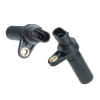

This guide addresses the reliability and quality assurance considerations for the SENSOR HALL DIGITAL CONNECTOR (SKU: SD101201) manufactured by ZF Electronics. This component integrates a Hall effect sensor with a digital output and a connector interface, making it critical for position sensing in automotive, industrial, and consumer applications. Understanding its reliability profile is essential for minimizing field failures and ensuring long-term system performance.
Reliability Standards and Qualifications
ZF Electronics typically qualifies their Hall sensors under industry standard AEC-Q100 for automotive applications, though this specific SKU may also be tested to IPC-9592 for industrial power conversion equipment. Key qualification tests include: High Temperature Operating Life (HTOL) at 150°C for 1000 hours, Temperature Cycling (TC) from -55°C to 125°C for 1000 cycles, and Highly Accelerated Stress Test (HAST) at 130°C/85% RH for 96 hours. The connector interface should meet USCAR-2 or LV214 standards for electrical terminals, ensuring 100+ mating cycles without degradation. Ensure the supplier provides a full qualification test report or certificate of conformance (CoC) for the specific manufacturing lot.
Accelerated Life Testing and Results Interpretation
Accelerated life tests (ALT) for this Hall sensor often use Arrhenius modeling with an activation energy (Ea) of 0.7 eV for electromigration and 1.0 eV for oxide breakdown. A typical ALT applies 125°C ambient with 5V continuous bias for 2000 hours. The results are extrapolated to use conditions (e.g., 85°C ambient) to estimate lifetime. For example, if no failures occur in 2000 hours at 125°C, the estimated lifetime at 85°C is approximately 20 years. Pay close attention to the acceleration factor (AF) used; a higher AF implies greater stress, but results must be validated with failure analysis. If failures occur, examine for magnetic hysteresis drift, bond wire fatigue, or connector corrosion.
Failure Rate Calculations and MTBF Considerations
FIT (Failures In Time) rates for this component are typically calculated using Telcordia SR-332 or MIL-HDBK-217F models. For a Hall sensor, the base FIT rate is often 10-20 FIT at 40°C junction temperature, but this increases with temperature. A connector adds approximately 5-10 FIT per contact pin. For the SD101201, assuming a 4-pin connector and 85°C ambient, the total FIT rate can be estimated at 30-50 FIT. Mean Time Between Failures (MTBF) is calculated as 1,000,000 / FIT, yielding an MTBF of 20,000 to 33,333 hours. This is a statistical estimate; actual field MTBF may vary due to application-specific stresses like vibration, moisture, and voltage transients. Always request the supplier's FIT calculation report with the assumed duty cycle and ambient temperature.
Environmental Stress Screening and Burn-In Procedures
To weed out infant mortality failures, implement a burn-in procedure: apply rated voltage (typically 5V) at 85°C for 48 hours with continuous magnetic field cycling (e.g., 1 Hz square wave). Monitor the digital output for glitches, missing pulses, or excessive jitter. Environmental stress screening (ESS) should include 10 cycles of thermal shock from -40°C to 125°C with a 5-minute dwell, followed by random vibration (5-2000 Hz, 10 Grms) for 30 minutes per axis. After screening, re-test all electrical parameters per the datasheet, including supply current, output voltage low, and switching thresholds. Reject any units that show parameter drift beyond 10% of initial values.
Counterfeit Detection Methods Specific to This Component Type
Hall sensors with digital connectors are susceptible to counterfeiting due to their high demand. Use these detection methods: Visual inspection for non-uniform molding, misaligned pins, or incorrect markings on the ZF logo and date code. Measure the magnetic switch point (Bop and Brp) using a calibrated Helmholtz coil; authentic parts have tight tolerance (<5% variation). Perform X-ray inspection to verify the die size and bond wire configuration—counterfeits often use smaller dies or different wire materials. Verify the connector terminal plating (e.g., gold or tin) using XRF analysis; counterfeit terminals may have substandard plating thickness. Finally, cross-reference the part number and date code with ZF Electronics' official distribution records. If the lot is from a non-authorized source, conduct a full electrical test at temperature extremes.
Incoming Inspection Best Practices
Upon receipt, inspect the SD101201 for: Physical damage to the connector housing, bent or corroded pins, and contamination on the sensing face. Verify the packaging is ESD-safe and sealed per JEDEC J-STD-033. Perform a functional test on a sample (e.g., 20 pieces from each lot) using a known magnetic field source; measure the digital output state (high/low) at specified magnetic flux densities (e.g., 15 mT for turn-on, 5 mT for turn-off). Check the supply current at 5V to ensure it is within the datasheet limit (typically <10 mA). Document results in a lot traceability log, including supplier batch number and date of manufacture. Reject any lot with more than 1% parametric failures.
Storage and Handling Requirements to Maintain Reliability
Store the components in a dry, nitrogen-purged environment at 15-25°C and <60% relative humidity per IPC/JEDEC J-STD-033 for moisture-sensitive devices (MSL level 3 or higher). Use ESD-safe bags and trays; avoid exposure to strong magnetic fields (>50 mT) which can permanently alter the sensor's magnetic behavior. Handle by the connector body only to avoid stress on the pins. If the components are stored for more than 12 months, re-qualify with a bake-out at 125°C for 24 hours before assembly to remove moisture absorption. For automated pick-and-place, use compliant nozzles to avoid cracking the sensor package.
End-of-Life Management and Obsolescence Planning
ZF Electronics typically provides 5-10 years of active production for Hall sensor products. Monitor obsolescence notices through their official PCN (Product Change Notification) system. For long-life programs, maintain a 2-3 year buffer stock of the SD101201, stored under controlled conditions. When planning for end-of-life, identify alternative parts with compatible pinouts, switch points, and output types (e.g., open-drain vs. push-pull). Conduct qualification testing for any substitute, including mechanical fit, thermal performance, and system-level EMI compatibility. Consider a last-time buy (LTB) covering 5-10 years of projected demand, and work with authorized distributors to secure allocated inventory. Document all obsolescence decisions in the Bill of Materials (BOM) with approved replacement paths. Proactive monitoring of supplier roadmaps is essential to avoid costly redesigns or supply chain disruptions.