
The RHC50-15-500K-RC, a 50µH, 10% tolerance, 15A radial high-current inductor from Allied Components International, is a passive component critical in power supply filtering, DC-DC converters, and energy storage applications. Its reliability is paramount for professional electronics procurement, where system uptime and safety are non-negotiable. This guide addresses key quality and reliability considerations for this specific part, which is manufactured to industry-standard specifications but lacks a dedicated military or automotive qualification. The component typically conforms to generic passive component reliability standards such as AEC-Q200 (if specified by Allied for certain lots, though not guaranteed for this SKU) and general IPC/JEDEC standards for solderability and mechanical robustness. For most commercial and industrial applications, the manufacturer’s internal qualification based on JIS C 4121 or similar guidelines for ferrite core inductors is sufficient. However, procurement professionals must verify that the supplier provides a Certificate of Conformance (CoC) and a detailed data sheet outlining maximum ratings, operating temperature range (-40°C to +125°C typical), and insulation resistance.
Accelerated life testing (ALT) is essential to estimate the useful life of this inductor under normal operating conditions. For this component, ALT typically employs high-temperature operating life (HTOL) tests at 125°C ambient with rated DC current (15A) plus a superimposed AC ripple current at the rated frequency (often 100kHz). The test results are analyzed using the Arrhenius model to extrapolate failure rates. A common acceleration factor is derived from a temperature rise of 10°C doubling the failure rate (the 10°C rule of thumb for electrolytic capacitors, but for ferrite inductors, a more conservative 15-20°C rule applies due to core saturation effects). Results from 1000-hour tests with zero failures indicate a predicted failure rate below 1 FIT (failures per billion hours) at 40°C junction temperature. However, because this is a passive magnetic component, failure modes include open windings, shorted turns, or core fracture, all of which are temperature and current dependent. ALT data should be requested from the manufacturer, particularly for lot acceptance testing (LAT) of critical batches.
Failure rate calculations for this inductor are based on the MIL-HDBK-217F or Telcordia SR-332 reliability prediction models. For a ferrite core inductor in a grounded, fixed environment (ground benign, GB), the base failure rate is approximately 0.1 to 0.5 FIT per device. However, this must be multiplied by application-specific factors: electrical stress (voltage and current derating), ambient temperature, and quality factor (πQ) for the component’s manufacturing quality. For the RHC50-15-500K-RC, assuming 50% derating on current (7.5A operating) and 60°C ambient, the predicted FIT rate is typically around 0.2 to 0.8 FIT, corresponding to an MTBF (Mean Time Between Failures) of 1.25 billion to 500 million hours. These predictions are theoretical and assume no infant mortality. Practical MTBF for high-current inductors is dominated by solder joint fatigue and core aging, so actual field data may show lower MTBF values. Procurement should require the supplier to provide FIT rate documentation based on their own testing or industry-standard models.
Environmental stress screening (ESS) and burn-in procedures for this component are less common than for active semiconductors, but still beneficial for high-reliability applications. A recommended burn-in profile includes a 48-hour period at 85°C ambient with a continuous DC current of 15A (or 80% of rated current to avoid accelerated degradation) while monitoring inductance and DC resistance (DCR) at intervals. After burn-in, a 100% measurement of inductance at 1kHz and DCR at 25°C is performed. Components showing a change in inductance greater than ±5% or DCR increase of more than 10% should be rejected. Temperature cycling (10 cycles from -40°C to +125°C with 15-minute dwells) followed by a functional test can screen out mechanical defects such as cracked cores or poor wire-to-terminal bonds. For less critical applications, a simpler 24-hour burn-in at 125°C without current is acceptable to stabilize the ferrite material.
Counterfeit detection for radial high-current inductors requires careful visual inspection and electrical testing. Common counterfeits include re-marked or re-packaged parts from unknown sources. Specific methods for this component include: verifying the manufacturer’s logo and part number (Allied Components International) with a 10x microscope to ensure consistent font, spacing, and no evidence of laser etching or sanding. The ferrite core should be uniform in color and free of pitting. Measure the inductance at 1kHz and 100kHz using an LCR meter; counterfeit parts often show out-of-spec inductance or high DCR due to inferior winding wire. A saturation current test (applying DC current until inductance drops by 10%) should match the datasheet value of typically >20A. Additionally, a thermal imaging test during rated current operation can reveal hot spots from poor core or winding quality. Always purchase from authorized distributors like DigiKey or Mouser to minimize counterfeit risk.
Incoming inspection best practices for this inductor include a sampling plan per AQL 1.0 (normal level II) for critical parameters. Perform the following checks: visual inspection for cracks, terminal integrity, and lead solderability (per J-STD-002). Measure inductance at 1kHz and 10% tolerance (47µH to 53µH) using a calibrated LCR meter. Measure DCR at 25°C; the datasheet specifies a maximum value (typically <0.05Ω for this part). Measure saturation current by ramping DC current until inductance drops 10%. Perform a high-potential (hi-pot) test at 500VAC for 1 second between windings and core to ensure insulation integrity. For large lots, a sample of 20 pieces should undergo thermal shock (10 cycles, -40°C to +125°C) with post-test inductance and DCR re-measurement. Document all results in a lot traceability system.
Storage and handling directly affect the long-term reliability of ferrite core inductors. Store in original anti-static packaging at 15-35°C and 30-70% relative humidity. Avoid exposure to corrosive gases like sulfur, chlorine, or ammonia, which can degrade the ferrite material and reduce inductance over time. The components should be kept on reels or trays, not stacked under heavy loads that could crack the cores. Handling should be done with ESD-safe tweezers or vacuum pickups to avoid mechanical stress on the leads. If stored for more than 12 months, bake at 60°C for 24 hours before assembly to remove moisture absorbed by the ferrite, which can cause solderability issues or internal corrosion.
End-of-life (EOL) management for this specific SKU requires proactive obsolescence planning. Allied Components International may discontinue this part with a 90-day notice. Procurement should maintain a buffer stock of 6-12 months of forecasted demand. Identify alternate sources or drop-in replacements (e.g., Bourns, Coilcraft, or Wurth Elektronik inductors with identical footprint and ratings). For long-life systems, design in a form-fit-function alternative with equal or better specifications. Regularly check the supplier’s EOL notifications and maintain a qualified parts list (QPL) with second-source options. When the part is no longer available, consider last-time buy (LTB) quantities for the remaining product lifecycle, with proper storage to maintain reliability over extended periods.

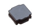
50UH 10% 15AMP RADIAL HI.CURR.
Allied Components International | RHC50-15-500K-RC | $4.50