When debugging circuits that incorporate the 469/453as-timken taper roller bearing, it is critical to understand that this is a mechanical component, not an electronic one. The bearing is used in rotating assemblies, often within motor drives, gearboxes, or spindle systems that interface with electronic controls. The most common failure modes are mechanical, but they manifest as electrical symptoms, such as erratic motor current, vibration-induced noise on sensor lines, or complete system lockout.
Typical failure modes and their root causes include overheating, which often stems from improper preload or lubrication starvation. If the bearing runs hot, the internal clearance can collapse, leading to skidding or spalling. Another common failure is vibration and noise, caused by misalignment of the shaft or housing, or by contamination from debris. In circuits, this vibration can cause intermittent connections in nearby solder joints or induce microphonic noise in sensitive analog inputs. A third failure is premature wear or brinelling (indentations on the raceway) due to shock loads or incorrect mounting practices.
Step-by-step debugging methodology should begin with a visual inspection. Look for discoloration around the bearing housing, which indicates overheating. Check for axial or radial play by gently prying on the shaft with a dial indicator. Next, perform a rotational test by hand; the bearing should turn smoothly with no gritty feeling. Then, use a stethoscope or a simple screwdriver pressed to the housing while the system runs to detect abnormal sounds. Finally, correlate any mechanical anomalies with electrical symptoms, such as a rise in motor current draw or noise spikes on an encoder signal.
Common mistakes in schematic design and PCB layout often involve ignoring the bearing’s mechanical footprint. For example, designers may place decoupling capacitors or signal traces too close to the bearing housing, where vibration can fatigue the solder joints. Another mistake is failing to provide a proper ground path for the bearing’s metallic housing, which can lead to electrical noise coupling into the circuit. In layouts for motor drivers, the high-current traces should be routed away from the bearing’s mechanical path to avoid inductive heating. Always include mechanical standoffs or vibration dampers in the PCB mounting strategy.
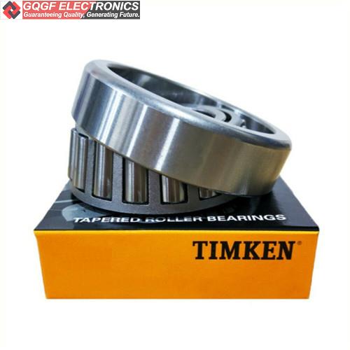
How to verify component authenticity and quality is crucial with bearings, as counterfeit parts are common. Start by measuring the dimensions with a micrometer; the 469/453as-timken should exactly match 2.25 inches outer diameter, 4.25 inches inner diameter, and 1.0939 inches width. Check the Timken laser engraving for clarity and depth—counterfeits often have blurred or shallow markings. Weigh the bearing on a precision scale; a genuine unit will have a consistent weight, typically around 0.8 pounds. Also, inspect the rollers and raceways for a polished, mirror-like finish. If possible, compare the part’s noise signature using an accelerometer against a known good sample.
Measurement techniques and test equipment should focus on both mechanical and electrical parameters. Use a dial indicator and a bearing puller to measure axial and radial play. For electrical debugging, employ an oscilloscope with a current probe to capture motor current waveforms; a failing bearing will cause periodic current spikes at the shaft rotation frequency. A spectrum analyzer or an FFT function on a scope can reveal vibration frequencies from bearing faults. A thermal imaging camera is invaluable for spotting hot spots on the bearing housing or nearby PCB components. For noise coupling, a differential probe on the encoder lines can show induced voltage from mechanical vibration.
When to suspect the component vs. the surrounding circuit requires a systematic approach. First, if the system exhibits symptoms only during rotation (e.g., noise at a specific RPM), the bearing is more likely the culprit. If the symptoms are present even when the shaft is stationary, the circuit or power supply is usually at fault. A good test is to disconnect the mechanical load and spin the bearing by hand while monitoring the circuit’s output. If the noise or current spike disappears, the bearing is likely the root cause. Conversely, if the issue persists with the bearing removed, focus on the electronics.
Real-world case studies illustrate common problems. In one case, a customer reported intermittent motor stall in a CNC spindle. The motor driver’s current sense resistor was overheating. After swapping the bearing, the issue vanished. The root cause was a worn 469/453as-timken that caused increased friction, drawing excess current. Another case involved a robotic arm with encoder jitter. The bearing was properly installed, but the PCB was mounted directly to the housing without vibration isolation. The solution was to add rubber grommets between the PCB and the bearing housing, which eliminated the microphonic noise. A third case was a false counterfeit alarm: a customer complained that the bearing was noisy out of the box. Upon inspection, the bearing was genuine, but the shaft had a burr that was damaging the inner race. Deburring the shaft solved the problem.
In summary, successful debugging of a 469/453as-timken bearing circuit hinges on understanding that the bearing’s mechanical health directly impacts electrical performance. Always start with mechanical checks, verify authenticity with precise measurements, and isolate the bearing by decoupling it from the circuit during tests. By following these practical steps, you can quickly distinguish between a failing bearing and a circuit design flaw.
469/453as-timken
Timken | 469/453as - Timken Taper Roller Bearing - 2.25x4.25x1.0939inches | $511.63