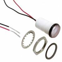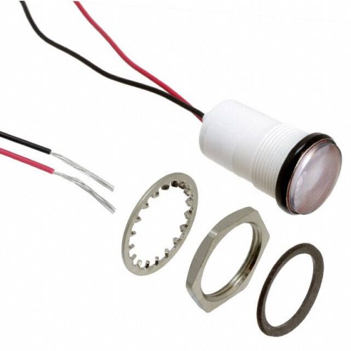

This guide addresses the reliability and quality assurance considerations for the Dialight LED Mini Panel Indicator, Yellow, 28V (SKU: 5571304203F). This component is a solid-state, high-reliability indicator typically used in aerospace, defense, industrial control, and medical instrumentation. Its performance and longevity depend on strict adherence to qualification standards, handling procedures, and ongoing quality monitoring.
Reliability Standards and Qualifications: This Dialight component is designed to meet or exceed MIL-DTL-3661 and MIL-PRF-19500 standards for panel indicators. Key qualifications include resistance to shock (per MIL-STD-202, Method 213), vibration (Method 204), and moisture resistance (Method 106). The yellow LED die itself should be qualified to JEDEC standards, particularly JESD22 for temperature cycling and AEC-Q102 (if applicable for automotive-grade variants). The complete assembly is typically rated for an operating temperature range of -55°C to +85°C. Ensure that any supplier certificate of conformance (CoC) explicitly references these standards, as they are the baseline for acceptance in critical applications.
Accelerated Life Testing and Results Interpretation: Accelerated life testing (ALT) for this LED indicator is performed using elevated temperature and current stress, often following the Arrhenius model or the Eyring model for combined stresses. Typical ALT conditions include a junction temperature of +85°C with a forward current 1.5 times the rated maximum (e.g., 30mA for a 20mA nominal part). Results are extrapolated to normal operating conditions using an activation energy (Ea) of 0.6 eV to 0.7 eV for LED die degradation. A standard ALT run of 1,000 hours at +85°C might correlate to over 100,000 hours at +25°C. The primary failure mechanism is lumen depreciation (light output reduction) rather than catastrophic failure. A 50% reduction in luminous intensity is the typical end-of-life criterion. ALT results should confirm that the component maintains >70% of initial brightness after 10,000 hours at rated current and 25°C ambient.
Failure Rate Calculations (FIT Rates) and MTBF Considerations: For this solid-state component, the failure rate is expressed in FITs (Failures In Time per billion device-hours). Based on MIL-HDBK-217F, a single yellow LED in a hermetic package at 25°C base temperature has a FIT rate typically between 10 and 50 FITs. The 28V integrated resistor and wire-bond connections contribute additional FITs, bringing the total for the panel indicator assembly to approximately 50-150 FITs. This translates to a Mean Time Between Failures (MTBF) of 6.7 million hours to 2 million hours. These calculations assume a constant failure rate (flat portion of the bathtub curve) and do not account for infant mortality, which is addressed through burn-in. For mission-critical applications, use a 60% confidence level and derate the MTBF by a factor of two to account for environmental stress (e.g., vibration, humidity).
Environmental Stress Screening and Burn-In Procedures: To eliminate infant mortality, a 48-hour burn-in at +70°C with a forward current of 28mA (for a 28V part) is recommended. This screen will reveal wire-bond failures, die attach voids, and solder joint defects. Follow this with five temperature cycles from -55°C to +85°C (10°C/minute ramp rate, 15-minute dwells) per MIL-STD-883, Method 1010, Condition B. After screening, perform a 100% electrical test at room temperature, verifying forward voltage (Vf) tolerance of ±0.2V and luminous intensity within ±30% of datasheet values. A 100% visual inspection under 10x magnification for package cracks, resin bubbles, or lead corrosion is mandatory.
Counterfeit Detection Methods Specific to This Component: The Dialight 5571304203F is a high-value part, making it a target for counterfeiting. Key detection methods include: 1) Visual inspection of the marking – genuine parts have laser-etched, high-contrast part numbers and date codes; counterfeits often use ink printing that smears or is misaligned. 2) X-ray fluorescence (XRF) to verify lead finish composition – authentic parts have a matte tin or gold-plated lead finish compliant with RoHS. 3) Decapsulation using nitric acid to expose the LED die – genuine parts have a single, square die with a specific gold bond wire configuration; counterfeits may have a different die size or multiple bond wires. 4) Scanning acoustic microscopy (SAM) to detect internal voids or delamination in the epoxy encapsulation. 5) Electrical testing at 28V – measure the forward current; a genuine part should draw 20mA ±2mA. Counterfeits often have incorrect resistor values resulting in current draws of 10mA or 30mA.
Incoming Inspection Best Practices: Upon receipt, verify the following parameters on a 10% sample (or 100% for critical applications): Luminous intensity at 28V using a calibrated photometer with a 1m distance. Forward voltage at 20mA (should be 2.0-2.4V). Wavelength – yellow should be 585-595nm. Package dimensions – check the panel cut-out diameter (typically 0.375 inches) and the lead length. Date code – ensure the component is less than 24 months old from the date of manufacture to avoid storage-related degradation. ESD sensitivity – this LED is typically rated Class 1C (1000V to 2000V HBM); use a handheld ESD tester to verify that the part survives a 1000V discharge. Any part failing these tests must be quarantined and returned to the supplier.
Storage and Handling Requirements to Maintain Reliability: Store these indicators in a dry, nitrogen-purged environment at 15°C to 25°C with relative humidity below 30%. Dialight components are not typically moisture-sensitive (MSL Level 1), but prolonged exposure to humidity can oxidize the leads. Use ESD-safe trays or conductive foam to prevent damage from electrostatic discharge. Handle leads by the body, never by the leads, to avoid bending or stress cracking. Soldering should be done with a temperature-controlled iron at 350°C for no more than 5 seconds per lead, or via wave soldering at 260°C peak for 10 seconds. Avoid thermal shock—allow the part to cool slowly after soldering. Cleaning should use isopropyl alcohol only; no chlorinated solvents, which can attack the epoxy lens.
End-of-Life Management and Obsolescence Planning: Dialight typically offers long-term support for these indicators, but LED die suppliers may discontinue yellow phosphors. Proactively request a Product Change Notification (PCN) from your distributor. Maintain a 2-year buffer stock for active projects. If the component is declared obsolete, identify a form-fit-function replacement such as the Dialight 558 or 559 series, or a directly pin-compatible LED from other MIL-qualified manufacturers. For existing designs, consider a last-time buy (LTB) covering 5 years of projected usage plus 20% for repair stock. Perform a reliability requalification on any substitute part, including 1000-hour ALT and thermal cycling, before changing the BOM. Document all obsolescence decisions in a formal component risk assessment report.