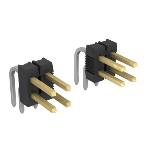
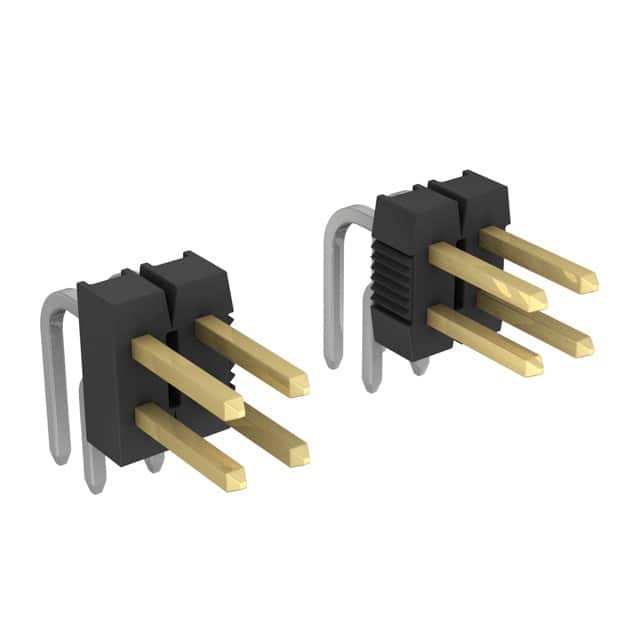
The 9-102975-0-04 from TE Connectivity AMP Connectors is a robust, 8-position, right-angle (R/A) header with a 2.54mm pitch, a staple in board-to-board and wire-to-board interconnects for industrial, automotive, and consumer electronics. To leverage this component effectively, a deep dive into its datasheet is essential, focusing on electrical, mechanical, and thermal parameters that dictate real-world performance.
Key Electrical Specifications and Practical Implications The datasheet for a 2.54mm pitch header like the 9-102975-0-04 will specify a current rating, typically around 3A per contact at a 30°C temperature rise, and a voltage rating of 250VAC/DC. In practice, this current rating is a thermal limit under ideal conditions, meaning a single contact carrying 3A in a 22°C ambient will rise to 52°C. However, when all eight pins are loaded, mutual heating reduces the safe continuous current per pin to perhaps 1.5-2A. The voltage rating, often tested at sea level, must be derated for altitude or high humidity to prevent arcing. The contact resistance is another critical specification, usually in the low milliohm range (e.g., 10mΩ max initial). A higher resistance increases I²R losses and local heating, so engineers should monitor this over lifetime as a wear-out indicator, especially in high-vibration environments where fretting corrosion can occur. The insulation resistance, typically 1000MΩ minimum at 500VDC, ensures negligible leakage between adjacent pins, crucial for high-impedance circuits like sensor inputs.
Absolute Maximum Ratings and Derating Considerations The absolute maximum ratings on the datasheet are not operating conditions but stress limits. For this header, the maximum operating temperature is often rated at 105°C or 125°C, with a storage range from -40°C to 125°C. Exceeding the maximum temperature, even momentarily, can soften the housing material (typically a high-temperature thermoplastic like LCP or PA9T), leading to pin retention loss or solder joint failure. Derating is mandatory: a safe practice is to operate at no more than 80% of the rated current at the maximum ambient temperature. For example, if the ambient is 85°C and the derating curve shows a 30% reduction, the safe per-pin current drops to 2.1A from 3A. Voltage derating is equally important; for applications above 2,000 meters altitude, the voltage rating may need to be halved to avoid corona discharge. The datasheet may also specify a maximum insertion force per pin (e.g., 1.5 N) and a minimum withdrawal force (e.g., 0.3 N), ensuring reliable contact under shock and vibration. Exceeding the insertion force limit can stress the housing, while too low a withdrawal force indicates worn contacts.
Typical Application Circuit Analysis The 9-102975-0-04 is commonly used as a parallel or right-angle connection for ribbon cables, discrete wires, or as a shunt for programming headers. In a typical application, such as connecting a sensor array to a microcontroller, the header’s pins are assigned as signal and ground pairs. For instance, pins 1, 3, 5, 7 might carry digital signals, while pins 2, 4, 6, 8 are ground. The datasheet’s layout guide recommends 0.8mm to 1.0mm diameter plated-through holes on a 2.54mm grid, with a solder fillet height of 0.5mm minimum for mechanical strength. For high-speed signals, the right-angle geometry introduces a small inductance (approximately 1 nH per mm of pin length) and capacitance (about 0.5 pF between adjacent pins), which can affect signal integrity above 10 MHz. A practical circuit analysis would involve adding a 10-100 pF bypass capacitor near the header’s power and ground pins to decouple noise. The header’s 2.54mm pitch is compatible with standard IDC sockets, but ensure the mating connector’s keying feature aligns; the datasheet often includes a mating face view showing the pin numbering (1 to 8 from the keying notch).
Pin Configuration and Package Considerations The 8-position, right-angle header has two rows of four pins each, with a polarization notch to prevent reverse insertion. The pin configuration is typically 1, 3, 5, 7 in one row and 2, 4, 6, 8 in the other, but verify the datasheet’s top and side views. The package is a through-hole design with solder tails of 3.0mm to 3.5mm length, designed for a 1.6mm thick PCB. The right-angle form factor places the pins parallel to the board, saving vertical space. The housing includes standoffs to allow flux cleaning and prevent solder wicking up the pin. Footprint dimensions are critical: the recommended PCB layout shows a 2.54mm pitch in both X and Y axes, with a 3.8mm to 4.0mm distance from the housing to the first row of holes. The datasheet may specify a maximum coplanarity of 0.1mm to ensure all pins contact the PCB evenly during wave soldering. For high-reliability applications, consider using a header with a locking ramp, though the 9-102975-0-04 is a standard unshrouded type; if mating with a locking socket, ensure the socket has a latch that engages the header’s notch.
Thermal Management Guidelines The primary heat source in this connector is resistive heating at the contact interface and the solder joint. The datasheet’s temperature rise curve shows that at 3A per pin, the contact temperature rises 30°C above ambient in still air. For effective thermal management, ensure adequate airflow around the header, especially if multiple adjacent connectors are used. The PCB copper planes act as heatsinks; a 1oz copper trace connecting the header’s ground pins can reduce the temperature by 10-15%. Avoid routing heat-sensitive components like electrolytic capacitors within 5mm of the header if it carries high current. The housing’s plastic material has a low thermal conductivity, so heat dissipation primarily occurs through the pins and PCB. In high-current designs (e.g., 2A per pin for all eight), consider using a header with a metal shield or adding a thermal pad under the housing, though this may require a custom variant. The datasheet may also specify a maximum soldering temperature of 260°C for 10 seconds for lead-free processes; exceeding this can deform the housing or degrade the pin plating.
Interpreting Timing Diagrams and Characteristic Curves The 9-102975-0-04 is a passive component, so timing diagrams are not applicable. However, the datasheet provides characteristic curves such as current derating versus ambient temperature, contact resistance versus number of mating cycles, and insertion/withdrawal force versus life cycles. The derating curve typically shows a linear decrease from 100% rated current at 20°C to 50% at 105°C. For example, at 85°C, the curve indicates a 70% factor, so 3A * 0.7 = 2.1A per pin. The contact resistance curve should show a plateau for the first 100 cycles, then a gradual increase due to wear of the gold or tin plating. A sudden spike above 20mΩ after 500 cycles signals imminent failure. The insertion force curve typically exhibits a wear-in period where force decreases slightly, then stabilizes. Engineers should use these curves to set lifetime test criteria; for instance, if the application requires 200 mating cycles, ensure the contact resistance remains below 15mΩ. The voltage withstand curve shows maximum voltage versus altitude; at 3,000 meters, the 250V rating may drop to 150V. Always cross-reference these curves with the operating environment to avoid premature failure.
By systematically analyzing these datasheet sections—electrical limits, derating, application circuits, pinout, thermal constraints, and characteristic curves—engineers can confidently integrate the 9-102975-0-04 into their designs, ensuring reliability and performance over the product lifecycle.