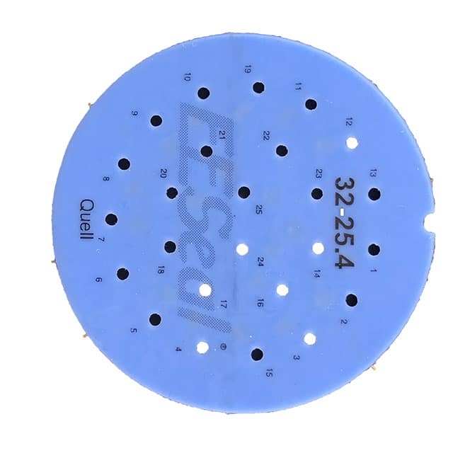
The Quell FCQ38999/20SG11PEMIL-STD-461 is not a conventional active component, but rather a precision-engineered electromagnetic interference (EMI) filter disk designed specifically for integration within a MIL-DTL-38999 Series III circular connector. Its primary function is to provide feed-through filtering at the connector interface, effectively suppressing conducted and radiated emissions to meet MIL-STD-461 requirements. The SKU suffix "20SG11PE" indicates the connector shell size (20), the insert arrangement (S for standard layout), and the specific pin count and gauge (11 pins, size #20), which dictates the mechanical footprint. Understanding this component begins with recognizing that its "electrical specifications" are not those of a standalone IC but rather the parasitic and filtering characteristics of a capacitive network embedded in a ceramic disk.
The key electrical parameter is the capacitance value per line, typically specified in picofarads (pF) with a tolerance, and the corresponding voltage rating, often 200 VDC or 50 VDC for signal lines. Higher capacitance (e.g., 1000 pF to 10,000 pF) provides greater low-frequency attenuation but introduces a lower self-resonant frequency, which can degrade high-frequency performance. In practice, this means a 4700 pF filter will offer excellent attenuation below 100 MHz but may become inductive above 1 GHz, allowing high-frequency noise to leak through. The insertion loss curve, typically plotted from 10 kHz to 10 GHz, is the critical performance metric. A well-designed disk will show a roll-off of 20 dB per decade above the cutoff frequency, with a minimum of 40 dB attenuation in the 100 MHz to 1 GHz range, which is the typical switching noise band for modern power converters.
Absolute maximum ratings for this filter are deceptively simple but critical for reliability. The maximum working voltage is the continuous DC or AC peak voltage that can be applied without dielectric breakdown. Exceeding this, even momentarily, can cause catastrophic shorting. The withstanding voltage (often 2.5 times the working voltage) is a one-time test condition, not a continuous operating point. Derating is essential: for a 200 VDC-rated disk, a conservative design should limit applied voltage to 80 VDC to account for transient spikes and aging of the ceramic dielectric, which can lose capacitance over time due to DC bias. Temperature derating is equally important. The disk is rated for operation from -55°C to +125°C, but capacitance stability is specified only within a narrower band (e.g., ±15% change from -55°C to +125°C for X7R dielectric). At high ambient temperatures combined with high current, the internal self-heating can shift the resonance point, reducing filtering effectiveness. Always derate current by 50% if the ambient temperature exceeds 85°C.
In a typical application circuit, the filter disk is mounted directly onto the back of the MIL-DTL-38999 connector's solder cup or PCB tail. The signal line passes through the center of the disk, which acts as a feed-through capacitor. The outer diameter of the disk is grounded to the connector shell, which is in turn connected to chassis ground. The critical analysis here is that the filter's performance is highly dependent on the grounding inductance. If the disk is not mounted with a low-impedance, 360-degree circumferential contact to the shell, the effective inductance in the ground path will resonate with the capacitance, creating a parallel resonance that actually amplifies noise at a specific frequency. A poor ground connection, such as a single solder tab, can ruin the filter's performance above 30 MHz. The circuit essentially forms a low-pass π-filter when combined with the source and load impedances. For a 50-ohm system, the -3 dB cutoff frequency is approximately 1/(2π 50 C). For a 4700 pF capacitor, this yields a cutoff of around 677 kHz, meaning signals below this frequency pass unimpeded, while higher frequencies are shunted to ground.
Pin configuration for this filter is dictated by the connector insert arrangement, not the disk itself. The "11" in the SKU indicates 11 pins, each with a dedicated filter element. The disk is a monolithic ceramic block with multiple through-holes, each plated to make contact with a corresponding pin. The package consideration is the mechanical thickness and hole tolerance. The disk must fit precisely within the connector's rear grommet cavity, with a tight tolerance on the hole diameter to ensure a snug, gas-tight fit against the pin. Any axial play will cause micro-phonics, where vibration modulates the capacitance, creating spurious signals. When integrating, the engineer must verify that the disk's outer diameter matches the connector shell's internal bore, and that the solder preforms (if used) have the correct melting point to avoid damaging the ceramic. The disk is not serviceable; it is a one-time press-fit or solder assembly.
Thermal management for this component is often overlooked because it is passive, but the ceramic material has poor thermal conductivity compared to metals. The primary heat source is not the filter itself but the adjacent power pins in the connector. If a neighboring pin carries 5A, the heat can conduct through the connector insert to the filter disk, causing differential thermal expansion between the ceramic and the metal pins. This mechanical stress can crack the ceramic, leading to a short circuit. The guideline is to maintain a maximum case temperature of 105°C at the disk's outer rim, measured with a thermocouple. If the connector is exposed to high ambient temperatures, derate the current on adjacent pins by 25%. Thermal cycling between -55°C and +125°C should be limited to 500 cycles, as repeated expansion can cause fatigue fractures in the solder joint connecting the disk's outer electrode to the shell.
Interpreting the characteristic curves for this filter requires a focus on the insertion loss versus frequency graph. The curve is not a straight line; it will show a dip (a resonance notch) at the self-resonant frequency. This dip indicates where the parasitic inductance of the disk's internal electrodes cancels the capacitance. Above this frequency, the slope reverses, and the filter becomes ineffective. The datasheet will also provide a capacitance change versus DC bias curve. For X7R dielectric, this curve shows a sharp drop in capacitance as DC voltage increases, often falling to 50% of nominal at rated voltage. This means if your application is a 28V DC power line, the effective capacitance is higher than if you use a 100V DC line. The timing diagrams are not applicable here; instead, look for the temperature coefficient curve, which shows capacitance drift versus temperature. A Class I dielectric (C0G) will be nearly flat, while a Class II (X7R) will vary by ±15%. For filter applications, the X7R is acceptable because the exact cutoff frequency is not critical, but you must account for this tolerance in your worst-case EMI margin analysis. Always compare the measured insertion loss at 25°C against the curve at 125°C; expect a 10 dB reduction in attenuation at high frequencies due to increased dielectric losses.