Recommended circuit topologies and design best practices
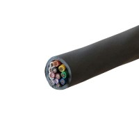
The Alpha Wire 77016 SL005 is a 12-conductor, 20 AWG, unshielded, slate-jacketed cable intended for general-purpose interconnection, signal routing, and low-power distribution. For most applications, treat this cable as a multi-drop bus or a point-to-point harness rather than a controlled-impedance transmission line. Because it is unshielded and has no twisted pairs, it is best suited for low-speed digital signals (below 1 MHz), analog signals with modest bandwidth (under 100 kHz), and DC power. For differential signaling, pair up conductors adjacent to each other (e.g., pins 1 and 2, 3 and 4) to minimize loop area, but do not expect matched impedance—keep trace lengths short and use series termination at the source if driving fast edges. For power distribution, use multiple conductors in parallel (e.g., three for VCC, three for GND) to reduce DC resistance and improve current handling; 20 AWG has approximately 10 mΩ/ft, so 100 feet yields about 1 Ω per conductor—plan voltage drops accordingly. Best practice is to separate noisy power lines from sensitive signal lines by at least one conductor, ideally dedicating an outer conductor to ground as a rudimentary shield.
Component selection guidelines for supporting passives
When designing the interface circuitry, choose series resistors (33–100 Ω) for each signal line to damp ringing and reduce EMI, especially if the cable length exceeds 10 feet. For power inputs, add a bulk capacitor (e.g., 47 µF electrolytic) and a 0.1 µF ceramic at the load end to decouple inductance. If you are driving relays, solenoids, or other inductive loads, place flyback diodes (1N4007 or Schottky) directly across the load terminals, not at the cable end. For analog signals, use a low-pass RC filter at the receiver with a cutoff frequency at least 3× above your maximum signal frequency—for example, 1 kΩ and 1 nF gives ~160 kHz. If you need overvoltage protection, add TVS diodes (e.g., SMAJ5.0A) from each conductor to ground; the cable itself has no shielding, so external transients couple easily. Avoid using the cable for high-impedance sensor inputs; instead, buffer with an op-amp (e.g., LM358) configured as a voltage follower to reduce susceptibility to noise pickup.
PCB layout recommendations and routing tips
On your PCB, bring the cable’s 12 conductors to a robust connector—preferably a screw terminal or a locking header—with a footprint that provides strain relief. Route traces from the connector to the driver/receiver ICs with minimum length and no sharp 90° corners; use 45° or curved bends. Keep critical signal traces away from the edge of the board, and place a ground plane (or at least a ground pour) directly beneath the connector area to provide a return path. If you have multiple boards in a daisy-chain, use a star topology from a single master to avoid ground loops. For the cable itself, when routing inside an enclosure, avoid running it parallel to AC mains wires; cross at 90° if necessary. At the PCB, add a 100 pF capacitor from each signal line to ground at the connector to filter RF—this is especially important for cables longer than 3 feet.
EMC/EMI considerations and mitigation strategies
Since this cable is unshielded, it acts as an efficient antenna for both radiated and conducted emissions. To mitigate EMI, the most effective approach is to use the cable as a balanced line: drive each signal with both a signal and its complement (e.g., RS-422 or LVDS, though LVDS is overkill for 20 AWG). If you must use single-ended signals, add a ferrite bead (e.g., 600 Ω at 100 MHz) on each conductor at the PCB entry point, and place a common-mode choke on the entire bundle if possible. For immunity, twist pairs of conductors manually before inserting into the jacket—this reduces differential-mode pickup. Always terminate unused conductors at both ends to ground (through 10 kΩ resistors) to avoid floating antenna segments. For radiated emissions, keep the cable length as short as practical; if 100 feet is mandatory, consider adding a ferrite clamp (snap-on) near each end. Also, ensure that the system chassis ground is connected to the cable’s drain wire—but note this cable has no drain, so use one of the 12 conductors as a dedicated ground return, and connect it to the PCB’s star ground point.
Common design pitfalls and how to avoid them
A frequent mistake is assuming all 12 conductors are identical and interchangeable—they are, but only if you label them clearly from the start. Without color coding, rework becomes impossible; use a marker or heat-shrink labels. Another pitfall is overloading the cable’s current capacity: 20 AWG is rated for about 11 A for chassis wiring, but when bundled with 11 other conductors, derate to ~5 A per conductor. Also, do not run AC power through this cable—it is not rated for mains voltage (use 300 V max, and even then only for DC). A classic error is neglecting the capacitance between conductors (~50 pF/ft for 20 AWG, giving ~5 nF over 100 ft); this will roll off high-frequency signals and cause crosstalk. To avoid, keep signal frequencies below 100 kHz and use the series resistor + capacitor filter at the load. Finally, do not bend the cable sharply (minimum bend radius is ~10× the diameter); repeated flexing will break individual strands.
Prototyping tips and bench testing procedures
Before committing to a full harness, cut a 10-foot sample and test it with your actual driver and receiver. Use a signal generator and oscilloscope to measure rise time degradation and crosstalk: apply a 1 kHz square wave to one conductor while monitoring adjacent conductors with a high-impedance probe. Record the amplitude of induced noise—if it exceeds 10% of the signal, add series resistance or reduce the drive current. For power lines, measure the voltage drop under full load using a four-wire Kelvin connection to avoid lead resistance errors. Test for EMI using a near-field probe (sniffer) connected to a spectrum analyzer; check for peaks at your clock frequency and its harmonics. When prototyping, terminate the far end with a dummy load (e.g., a 120 Ω resistor for RS-485) and verify signal integrity with an eye diagram. Also, perform a flex test: bend the cable 100 times at a 90° angle and re-measure resistance—any increase over 5% indicates a broken strand. Finally, document the pinout in a table and verify continuity with a multimeter before connecting to any powered circuit.