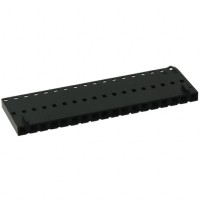
The Molex 0050579218 is a 18-position receptacle housing designed for 2.54mm pitch crimp terminal connectors, commonly referenced as a housing for the KK 254 series. This component is not a finished connector but a housing that requires separate crimp terminals to complete a wire-to-board or wire-to-wire connection. Understanding its datasheet is critical for ensuring reliable interconnection in applications ranging from consumer electronics to industrial control systems.
Key Electrical Specifications and Practical Meaning
The primary electrical specification for this housing is its current rating, which is typically listed as 2.5A per circuit maximum when used with appropriate terminals. In practice, this rating assumes a single circuit is fully energized under standard laboratory conditions at 20°C ambient temperature. Engineers must understand that this rating is not a guarantee for all configurations. The actual current capacity depends heavily on the number of circuits simultaneously carrying current, the wire gauge used, and the ambient temperature. For instance, if all 18 positions are loaded, derating factors apply due to mutual heating between adjacent terminals. A practical rule of thumb is to operate at no more than 60-70% of the rated current when all positions are active, especially in enclosed environments. The voltage rating, typically 250V AC/DC, assumes proper clearance and creepage distances are maintained, which are adequate for most low-power signal and power applications below 250V.
Absolute Maximum Ratings and Derating Considerations
The datasheet specifies absolute maximum ratings which should never be exceeded, even momentarily. For the 0050579218, the maximum operating temperature range is usually -40°C to +105°C, though this can vary slightly with terminal selection. Exceeding these limits can cause the housing material, typically nylon 6/6 or a high-temperature thermoplastic, to soften, deform, or lose its latching retention force. Derating is essential when operating near these limits. For high-temperature environments, the current rating must be reduced according to the manufacturer's derating curve. A common approach is to apply a 10% derating for every 10°C rise above 30°C ambient. Additionally, the housing's insulation resistance, typically 1000 MΩ minimum at 500V DC, must be considered in high-humidity conditions where moisture ingress can lower resistance and cause leakage currents. Engineers should also note that the housing is not designed for high vibration environments unless paired with a positive locking mechanism and appropriate terminal retention features.
Typical Application Circuit Analysis
In a typical circuit, this housing serves as the interconnect point between a printed circuit board header (such as the Molex 002218 series) and discrete wires. The circuit analysis must consider the contact resistance of each terminal, which is typically around 10-20 mΩ per contact. For a 18-position cable assembly carrying multiple signals, the total loop resistance includes two contacts per signal path (one at the receptacle, one at the header) plus the wire resistance. This is critical for low-voltage applications where voltage drop can interfere with logic levels. For example, a 3.3V logic signal passing through 18 inches of 28 AWG wire and two contacts could see a drop of 50-100 mV at 100 mA, which may be significant. The housing's built-in polarization features, such as a keying ramp, prevent misinsertion and ensure correct circuit mapping. In multi-conductor applications, engineers should verify that the wire insulation diameter is compatible with the housing's wire entry diameter, typically accepting 22-30 AWG wire with insulation up to 1.7mm.
Pin Configuration and Package Considerations
The 18-position housing uses a single row configuration with a 2.54mm pitch between adjacent cavities. The pin numbering is usually marked on the housing, starting from position 1 at the keying feature. The housing is offered in a panel-mount or free-hanging style, with optional mounting ears for secure attachment. The package is typically a plastic tray or bag containing 100 to 1000 units. Engineers must note that the housing does not include terminals; they must be ordered separately, such as the Molex 000858 series crimp terminals. The insertion and removal forces are specified in the datasheet, typically 1.5 to 3.5 lbs for insertion and 1.0 to 2.0 lbs for removal per contact. These forces affect assembly yield and maintenance cycles. For automated assembly, the housing's dimensions and tolerances must be verified against pick-and-place equipment specifications, though manual insertion is more common.
Thermal Management Guidelines
While the housing itself does not generate significant heat, it acts as a thermal interface between the terminals and the ambient environment. Heat is generated at the contact interface due to contact resistance. For high-current applications, it is advisable to avoid grouping multiple high-power circuits in adjacent positions to prevent hot spots. The datasheet may provide a temperature rise versus current curve, showing that at 2.5A per contact, a single contact may rise 30°C above ambient. With multiple contacts, the cumulative effect can exceed 50°C. Forced air cooling or spacing out power circuits can mitigate this. The housing material has a thermal conductivity around 0.2-0.3 W/mK, meaning it is a poor conductor of heat, so most heat dissipates through the wires themselves. Using larger wire gauges (e.g., 22 AWG instead of 28 AWG) improves heat dissipation from the terminals.
Reading Timing Diagrams and Characteristic Curves
The datasheet for this housing typically includes insertion and withdrawal force curves as a function of insertion cycles. These curves show that after 25-50 mating cycles, the contact force decreases by about 10-15%, which can increase contact resistance. Engineers should use these curves to estimate the expected lifetime of the connection in applications requiring frequent disconnection. Another important characteristic is the temperature rise versus current curve, which is usually linear up to the rated current. Interpreting this curve requires understanding that the ambient temperature baseline must be subtracted. For example, if the curve shows a 20°C rise at 2A, operating in a 60°C environment means the contact temperature reaches 80°C, which is within the housing's 105°C limit but close to the terminal's maximum. The datasheet may also include a derating curve for multiple circuits, showing that at 18 positions fully loaded, the maximum current per circuit may drop to 1.5A. These curves are derived from empirical testing and are essential for reliable design. Always use the worst-case curves for safety margins, and consider that real-world conditions like dust, corrosion, or vibration can degrade performance beyond datasheet values.