Introduction to the Component
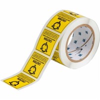
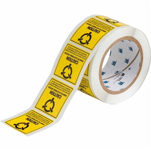
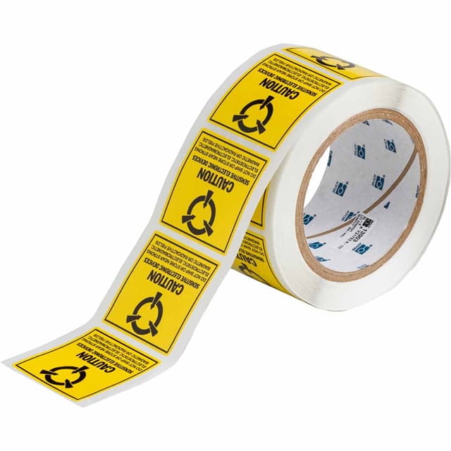
Every robust electronics design begins with clear identification. In this tutorial, we focus on a seemingly humble but critical component: the Brady Corporation SL-4 label, measuring 2 inches high by 2 inches wide. This self-laminating, polyester label is ideal for prototyping because it offers a durable, heat-resistant surface for marking wires, components, and test points. Its compact size fits standard terminal blocks and breadboard areas, while its aggressive adhesive ensures it stays put during repeated probing. What makes it perfect for our hands-on tutorial is its ability to survive soldering iron contact and cleaning solvents, allowing you to label your circuit without worry. We will use it to create a permanent, legible identification for a practical voltage regulator circuit.
Design Requirements and Specifications
We are designing a 5V, 1A linear voltage regulator powered from a 9V to 12V DC input. The circuit must provide clean, stable output with less than 50 mV of ripple and maintain regulation within ±2% under load. Key specifications include: input voltage range (9-12V), output voltage (5V ±0.1V), maximum output current (1A), dropout voltage (less than 2V), and operating temperature range (0°C to 50°C). The SL-4 labels will be used to mark input, output, ground, and test points on the PCB and on the heatsink for the regulator.
Step-by-Step Design Process with Calculations
First, select a regulator IC. The LM7805 in a TO-220 package is a classic choice. Calculate the dropout: at 1A, the LM7805 requires about 2V headroom. With a 9V input, we have 9V – 5V = 4V, which is sufficient. Next, compute power dissipation: P = (Vin – Vout) × Iout = (12V – 5V) × 1A = 7W worst-case. This requires a heatsink with thermal resistance below 10°C/W. Choose a 1000 µF electrolytic capacitor for input filtering (C1) and a 10 µF tantalum for output stability (C2). Add a 1N4007 diode for reverse polarity protection. Calculate the resistor for an LED indicator: assuming a 2V red LED at 10 mA, R = (5V – 2V) / 0.01A = 300 Ω.
Component Selection Rationale for the Complete BOM
The bill of materials is straightforward: LM7805 (U1) for its low cost and availability; 1000 µF, 25V electrolytic capacitor (C1) to handle input ripple; 10 µF, 16V tantalum capacitor (C2) for low ESR output performance; 1N4007 diode (D1) for rugged protection; 300 Ω, 1/4W resistor (R1); 5mm red LED (D2); a TO-220 heatsink rated at 8°C/W; a small PCB (prototyping board or custom layout); screw terminals for input and output; and of course, four Brady SL-4 labels to clearly mark “VIN,” “GND,” “VOUT,” and “HEATSINK.” The SL-4’s high-temperature polyester withstands the heatsink’s heat and the soldering process.
Simulation Tips and What to Look For
Simulate the circuit in LTspice or similar. Use a pulsed load stepping from 0A to 1A to examine transient response. Observe the output voltage spike—should settle within 50 µs. Look for ripple at 120 Hz (full-wave rectified input). Ensure the dropout voltage remains above 2V even at minimum input (9V). The simulation should show stable output with less than 50 mV ripple. If not, increase C1 to 2200 µF. The SL-4 labels are not simulated, but their placement on the PCB can be modeled as mechanical markers—just ensure no overlap with heat-sensitive components.
Prototype Build and Testing Methodology
Assemble the circuit on a perfboard. Start by soldering the LM7805 to the heatsink (use thermal paste). Then add the input capacitor, output capacitor, diode, and LED resistor. Use 20 AWG wire for power connections. After soldering, clean the board with isopropyl alcohol. Apply the Brady SL-4 labels: one near the input screw terminal (write “VIN” with a fine-tip permanent marker), one near output (“VOUT”), one near ground (“GND”), and one on the heatsink fin (“HS”). The labels should be placed on clean, dry surfaces; press firmly. Testing: apply 9V DC input via a bench supply. Measure output voltage—should be 5V ±0.1V. Test load regulation: connect a 5 Ω, 10W resistor (1A load) and verify output stays above 4.9V.
Performance Verification and Optimization
Use an oscilloscope to check output ripple: with a 1A load, ripple should be under 50 mV. If excessive, add a 0.1 µF ceramic capacitor in parallel with C2. Measure thermal performance: after 10 minutes at full load, the heatsink temperature should not exceed 70°C (use an IR thermometer). The SL-4 label on the heatsink must remain legible—if it starts to peel, the adhesive may be failing; ensure label placement avoids direct contact with the hottest fin. Optimize by increasing input capacitance or using a lower-dropout regulator like the LM2940 if needed. Finally, test short-circuit protection: momentarily short the output; the LM7805 should current-limit and survive. Re-label if any marking fades. The Brady SL-4 labels, with their durable construction, will outlast typical prototyping adhesives, making this circuit ready for permanent installation.