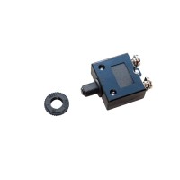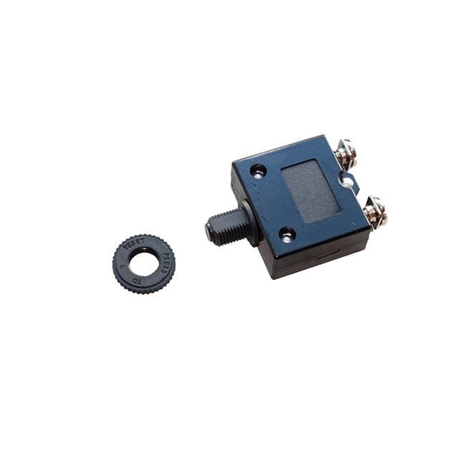
The OptiFuse CBW58-EL-40A is a thermal circuit breaker rated for 40A continuous current at 250VAC and 50VDC, designed to provide overcurrent protection in a variety of power distribution and industrial applications. Understanding its datasheet is critical for proper integration and reliable system performance. The primary electrical specification is the rated current of 40 amps, which defines the maximum steady-state current the breaker can carry without tripping under normal operating conditions, typically at an ambient temperature of 25°C. This is a continuous rating, meaning the breaker is expected to remain closed indefinitely at this current level, provided the ambient temperature does not exceed the specified reference point. The voltage ratings of 250VAC and 50VDC indicate the maximum system voltage the breaker can safely interrupt when a fault occurs. In practice, the AC rating is higher due to the natural zero-crossing of alternating current, which aids in arc extinction, while the DC rating is lower because direct current sustains an arc more persistently. For a 40A breaker, these voltage limits are typical for use in battery banks, power supplies, and low-voltage distribution panels.
Absolute maximum ratings are non-negotiable limits that must never be exceeded, even momentarily. For the CBW58-EL-40A, the maximum interrupting capacity is a critical parameter, often specified as a certain number of cycles at rated voltage. Exceeding this can cause catastrophic failure, such as arc flash or internal damage. Derating is essential when operating outside the ideal 25°C ambient. The datasheet typically includes a temperature derating curve, showing that as ambient temperature rises, the breaker’s effective trip current decreases. For example, at 60°C, the 40A breaker may trip at only 32A or less. Engineers must derate based on the worst-case ambient temperature inside the enclosure, considering heat from adjacent components. Additionally, derating for altitude is necessary if the system operates above 2000 meters, as thinner air reduces the dielectric strength and cooling efficiency. For continuous operation, a common practice is to load the breaker to no more than 80% of its rated current, especially in high-temperature environments, to prevent nuisance tripping and prolong lifespan.
Typical application circuits for the CBW58-EL-40A involve placing the breaker in series with the load, protecting the wiring and downstream components from overcurrent faults. The breaker is non-polarized, meaning it can be installed in either the positive or negative line of a DC circuit, or in the line conductor of an AC circuit. In a battery charging system, for instance, the breaker is placed between the charger output and the battery bank, sized to protect the charging cable from short circuits. For AC applications, such as motor control or lighting circuits, the breaker should be installed on the hot line before the switch or load. It is important to note that this is a thermal breaker, not a magnetic one, so it responds to the heating effect of current over time. This makes it suitable for protecting against sustained overloads but less effective for fast-acting protection against short circuits, which may require a supplementary fuse or a magnetic circuit breaker in series. The datasheet may also specify a maximum voltage drop at rated current, often around 100-200 mV, which is negligible but should be accounted for in low-voltage designs.
Pin configuration and package considerations are straightforward for this panel-mount breaker. The CBW58-EL-40A typically features two quick-connect terminals, such as 0.250-inch or 0.187-inch tabs, designed for use with mating female connectors. The package is a cylindrical or rectangular body with a threaded bushing for mounting through a panel cutout. The datasheet will provide a dimensional drawing showing the overall length, diameter, and thread pitch. Engineers must ensure the panel thickness and cutout size match the specified tolerances. For high-vibration environments, an additional lock washer or nut may be required to prevent loosening. The terminals are usually tin-plated brass, offering good conductivity and corrosion resistance. When wiring, it is critical to use appropriately sized conductors—for 40A, at least 8 AWG or 10 AWG depending on temperature rating and length—to avoid voltage drop and overheating at the connection points. The breaker’s internal bimetal strip and contact mechanism must be free from mechanical stress, so the mounting should not force the body out of alignment.
Thermal management guidelines are paramount because the breaker’s trip characteristic is inherently temperature-dependent. The datasheet provides a time-current curve, usually plotted on log-log axes, showing trip time versus current at various ambient temperatures. For the 40A model, at 125% of rated current (50A), the trip time might be 30-60 seconds, while at 200% (80A), it could be 5-15 seconds. This curve is based on a cold start at 25°C. If the breaker is exposed to elevated ambient temperatures from nearby power resistors, transformers, or poor ventilation, its thermal inertia decreases, leading to faster tripping. To mitigate this, ensure at least 10-15 mm of air gap around the breaker body, and avoid placing heat-generating components directly adjacent. Forced air cooling can help stabilize the ambient, but the breaker itself should not be subjected to airflow that cools the bimetal element, as this would shift its trip point. In high-density panels, consider derating the current further or using a breaker with a higher rating. The datasheet may also specify a thermal capacitance, which indicates how quickly the breaker responds to current pulses; this is useful for understanding its behavior during motor starting or inrush currents.
Interpreting timing diagrams and characteristic curves is the most nuanced aspect of the datasheet. The time-current curve for the CBW58-EL-40A typically shows a family of lines for different ambient temperatures, such as 25°C, 40°C, and 60°C. Each line represents the average trip time for a given multiple of rated current. For example, at 2x rated current (80A), the curve might indicate a trip time of 10 seconds at 25°C, but only 5 seconds at 60°C. Engineers must use this curve to verify that the breaker will not trip during normal transient events, such as capacitor charging or motor starts, which may draw 2-3 times rated current for a few seconds. The curve also shows a region of “no trip” below the rated current, usually up to 100-105% for indefinite periods. Additionally, a typical curve may include a “maximum trip” and “minimum trip” boundary, reflecting manufacturing tolerances. For the 40A breaker, the minimum trip time might be critical for coordination with downstream fuses or other breakers. Always use the worst-case (fastest trip) curve for system protection analysis, and the slowest curve for nuisance trip prevention. By overlaying the load’s current profile on this curve, you can confirm whether the breaker will clear a fault before damage occurs while avoiding unnecessary disconnection.