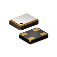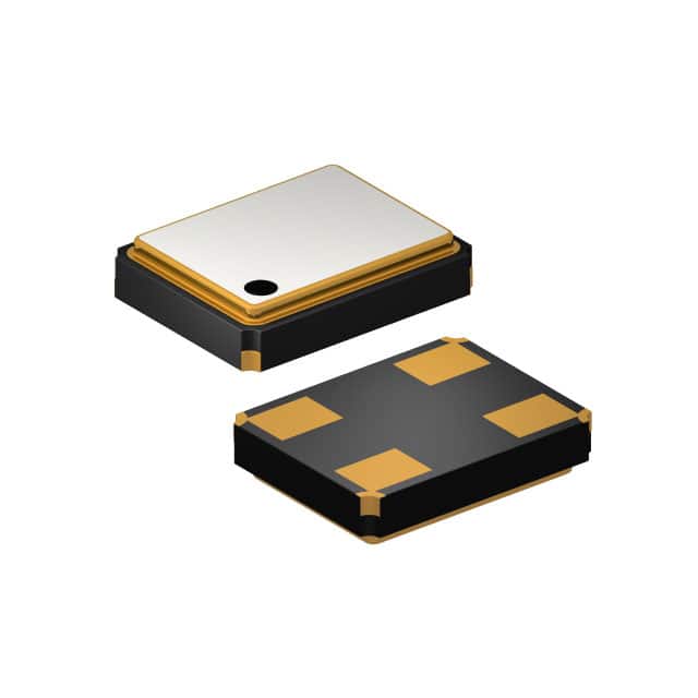
When selecting a timing reference for a precision digital system, a thorough understanding of the crystal datasheet is paramount. The Suntsu Electronics SXT32419CA17-16.000MT is a surface-mount quartz crystal resonator with a nominal frequency of 16.0000 MHz and a specified load capacitance of 19 pF. This component is a critical passive element for generating clock signals in microcontrollers, FPGAs, and communication interfaces. The first key specification to examine is the frequency tolerance, which is typically stated as ±10 ppm or ±20 ppm at 25°C. This tolerance defines the maximum allowable deviation from the nominal 16.0000 MHz frequency due to manufacturing variations. For applications requiring precise timing, such as USB or Ethernet, a tighter tolerance is essential to ensure data integrity. The frequency stability over temperature is another crucial parameter, often given as ±15 ppm or ±30 ppm across the operating temperature range (e.g., -20°C to +70°C). This accounts for the crystal's natural drift as its temperature changes. In practice, poor stability can cause the clock to drift outside the acceptable range for a UART or CAN bus, leading to bit errors.
The load capacitance (CL) specified as 19 pF is perhaps the most misunderstood parameter. This is not the capacitance of the crystal itself, but the total external capacitance that the oscillator circuit must present to the crystal for it to resonate at exactly 16.0000 MHz. The actual crystal's shunt capacitance (C0) is around 3 to 5 pF, and its motional capacitance (C1) is in the femtofarad range. To achieve the 19 pF load, you must place two external capacitors (C1 and C2) from each crystal pin to ground. The standard formula for a parallel resonant circuit is CL = (C1 * C2) / (C1 + C2) + Cstray, where Cstray is the parasitic capacitance from PCB traces and the IC pin (typically 2-5 pF). For a 19 pF load, if we assume Cstray = 3 pF, then C1 and C2 should each be around 33 pF. Using incorrect capacitor values will pull the frequency away from 16.0000 MHz, potentially causing system instability. The equivalent series resistance (ESR) is typically 40 to 60 ohms for this 16 MHz SMD crystal. A lower ESR is beneficial as it means less energy is dissipated as heat, making the oscillator start-up more reliable and reducing power consumption. High ESR can prevent oscillation entirely, especially in low-power designs.
The absolute maximum ratings must never be exceeded, even momentarily. The drive level, often specified as 100 µW maximum, is critical. Exceeding this can physically damage the quartz blank through mechanical stress, causing frequency shift or catastrophic failure. In practice, the drive level is determined by the oscillator amplifier's output power and the load capacitance. Derating is essential: operating at 80% of the maximum drive level is a common practice for long-term reliability. Similarly, the storage temperature range (-40°C to +85°C or wider) must be respected; extreme thermal shock can fracture the crystal. The aging specification, often ±3 ppm per year, must be factored into the system's total frequency error budget over the product's lifetime.
For the typical application circuit, the crystal connects directly to the oscillator input and output pins of a microcontroller or clock generator IC. A bias resistor (typically 1 MΩ) is often integrated inside the IC, but if not, it must be added in parallel with the crystal to bias the internal inverter into its linear region. The two external load capacitors, as calculated, are placed from each crystal terminal to ground. PCB layout is critical: the traces from the crystal to the IC should be as short as possible to minimize stray capacitance and noise coupling. A ground plane under the crystal area is recommended, but no other signal traces should run parallel to these sensitive lines.
The pin configuration for the SXT32419 series is straightforward: it is a 2-pin device (plus two ground terminals for mechanical stability in the SMD package). The package is a 3.2 mm x 2.5 mm ceramic SMD, which is ideal for space-constrained designs. Thermal management for a crystal is minimal; it does not generate significant heat itself. However, it must be placed away from heat sources like voltage regulators or high-power processors to avoid frequency drift due to thermal gradients. The crystal's frequency vs. temperature curve is typically parabolic, with the turning point near 25°C. Self-heating from the drive level is negligible if kept under 100 µW.
Reading the timing diagrams and characteristic curves is essential for advanced design. The datasheet will include a frequency vs. temperature curve, showing the parabolic deviation. For instance, at -20°C, the deviation might be -10 ppm, while at +70°C it might be +15 ppm. This curve allows you to calculate the worst-case frequency error over the entire temperature range. The start-up time is another important curve; it shows how long the oscillation amplitude takes to reach a stable level. For this 16 MHz crystal, start-up time is typically under 10 ms. A longer start-up than specified may indicate excessive load capacitance or weak oscillator drive. The drive level dependency graph illustrates how frequency shifts with applied power; this helps in ensuring the oscillator circuit operates within the safe linear region. Finally, the long-term aging plot (if provided) shows frequency drift over thousands of hours, which is critical for products with a 10-year lifespan. By cross-referencing these curves with your system's temperature and power requirements, you can confidently select the correct load capacitors and verify that the 16.0000 MHz crystal will maintain accurate timing throughout its operational life.