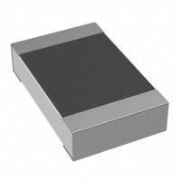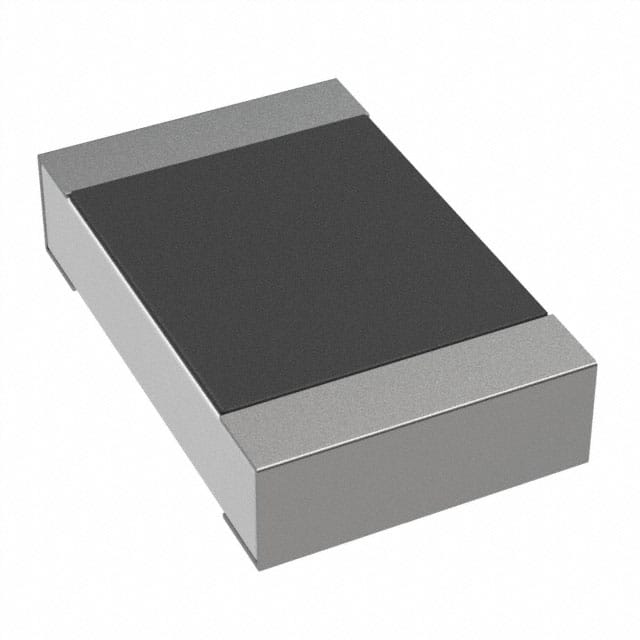
For the KOA Speer RK73B2ATTD153J, a 15kΩ ±5% 1/4W 0805 thick film resistor, the most robust circuit topologies include voltage dividers, pull-up/pull-down networks, current-limiting circuits, and feedback loops in operational amplifier configurations. When using this resistor in a voltage divider, ensure that the total power dissipation across both resistors does not exceed the 1/4W rating of the individual parts. For biasing applications, such as setting a reference voltage, place the resistor as close as possible to the input pin of the active component to minimize parasitic inductance and noise pickup. In digital pull-up or pull-down roles, a 15kΩ value is well-suited for standard logic families like 3.3V or 5V CMOS, providing a good balance between noise immunity and current consumption. Avoid using this resistor in high-frequency signal paths where its thick film construction introduces significant parasitic capacitance (typically 0.2–0.5 pF) and noise; for RF or high-speed digital circuits, prefer thin film or metal foil resistors. Always derate the power rating by at least 20% for ambient temperatures above 70°C, and by 50% if the resistor is adjacent to heat-generating components like power transistors or voltage regulators.
When selecting supporting passives for circuits using the RK73B2ATTD153J, prioritize capacitors with complementary temperature coefficients. For example, if the resistor is in a timing circuit, pair it with an NP0/C0G ceramic capacitor to minimize drift. For decoupling, use 0.1µF to 1µF X7R or X5R capacitors placed within 2mm of the resistor’s power supply node. Avoid using high-K dielectrics like Y5V or Z5U for precision analog circuits, as their capacitance varies significantly with voltage and temperature. If the resistor is part of a filter network, ensure that the capacitor’s self-resonant frequency is at least ten times the filter cutoff frequency to avoid unexpected phase shifts. For current-sensing applications, verify that the resistor’s ±5% tolerance is adequate; if higher precision is required, upgrade to a ±1% or ±0.5% part. Also, confirm that the supporting passives’ voltage ratings exceed the maximum applied voltage by at least 50% to prevent dielectric breakdown or premature failure.
For PCB layout, place the RK73B2ATTD153J on a solid ground plane to enhance heat dissipation, especially if it will operate near its 1/4W limit. Use wide, low-inductance traces (at least 0.5mm width for 1A pulse currents) and keep the resistor’s solder pads symmetrical to avoid tombstoning during reflow. Route the resistor’s connections with 45-degree or curved traces rather than sharp 90-degree corners to reduce signal reflections and electromagnetic radiation. For differential or matched resistor pairs, lay them out in a common centroid pattern to minimize thermal gradient effects and improve ratio accuracy. Avoid placing the resistor near the edges of the board or under large components that might shadow it from airflow. If the resistor is used in a high-voltage circuit (e.g., above 50V), increase the clearance between its pads and adjacent copper to at least 0.5mm, and consider adding a solder mask dam to prevent creepage. For multilayer boards, avoid running high-speed digital traces directly beneath the resistor on adjacent layers, as the resistor’s body can couple noise onto the trace.
Electromagnetic compatibility (EMC) and electromagnetic interference (EMI) considerations are critical when integrating the RK73B2ATTD153J. Its thick film construction inherently has higher noise (Johnson-Nyquist noise and flicker noise) than thin film or wirewound resistors, so for low-noise amplifier front-ends, use a metal film alternative. To mitigate conducted emissions, place ferrite beads or series resistors (like this 15kΩ part) in signal lines to dampen high-frequency ringing. For radiated emissions, ensure that the resistor’s leads are as short as possible—ideally, the resistor body should be directly soldered between two pads without long trace extensions. If the resistor is part of an RC snubber circuit across a switching node, select a resistor with a voltage rating that exceeds the peak switching voltage by at least 30%. Add a small capacitor (10–100 pF) in parallel with the resistor if it is used in a feedback path for a switching regulator, but only if the circuit stability allows. Finally, shield the resistor with a grounded copper pour if it is placed near a sensitive analog input or a high-speed digital line.
Common design pitfalls include exceeding the 1/4W power rating, especially in pulsed applications where the peak power is much higher than the average. Always calculate the RMS power for pulsed signals; for example, a 15V pulse across 15kΩ dissipates 15mW, but if the duty cycle is 50%, the average power is only 7.5mW—well within limits. However, a 50V pulse would yield 167mW, which is safe for short durations (less than 100ms) but could cause thermal runaway if repeated. Another pitfall is ignoring the resistor’s voltage coefficient—thick film resistors can exhibit a 1–5% resistance change at their maximum rated voltage (150V for 0805). For high-voltage designs, use multiple resistors in series to split the voltage. Avoid using this resistor in feedback loops of precision oscillators or analog filters where its ±5% tolerance and ±200 ppm/°C temperature coefficient (typical for thick film) will cause unacceptable drift. Also, do not rely on this part for current sensing in battery management systems where ±5% error translates to significant charge/discharge inaccuracies. Finally, ensure that the solder profile matches the resistor’s specifications: a peak reflow temperature of 260°C for 10 seconds maximum, and avoid rapid cooling to prevent microcracks in the ceramic substrate.
For prototyping, always start with a single RK73B2ATTD153J soldered onto a perfboard or breakout with short leads to minimize parasitic inductance. Use a precision multimeter (4.5-digit or better) to measure the actual resistance at room temperature before applying power. For bench testing of voltage divider circuits, apply a DC input and verify the output voltage ratio with a high-impedance oscilloscope probe (10MΩ or higher) to avoid loading. For transient tests, use a function generator with a 50Ω output impedance and a 10x passive probe; the resistor’s bandwidth is typically limited to a few hundred MHz due to its 0805 package. If testing in a power supply circuit, monitor the resistor’s temperature with a thermocouple or IR camera—if it rises above 85°C at full rated power, improve airflow or derate the power. For EMC testing, use a near-field probe to scan for hot spots around the resistor; if EMI is detected, add a 100pF capacitor in parallel or a ferrite bead in series. Document the measured resistance, temperature rise, and any drift after 1000 hours of accelerated life testing (85°C, 85% RH, full rated voltage) to validate reliability. Always keep spare parts in an ESD-safe bag until use, as thick film resistors can be damaged by electrostatic discharge above 1kV.