Introduction to the Component
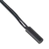
This tutorial focuses on the Littelfuse 59020-1-S-02-F, a SPST-NO (Single-Pole Single-Throw, Normally Open) reed switch with wire leads. This component is ideal for a hands-on design tutorial because it offers a perfect balance of simplicity and practical application. The reed switch consists of two ferromagnetic blades sealed in a glass tube. When a magnetic field is applied, the blades attract and close the circuit; when the field is removed, they spring back open. The wire leads make it easy to prototype on a breadboard or solder into a circuit. Its normally-open configuration is widely used for proximity sensing, door alarms, and position detection, making it a fundamental building block for many embedded systems.
Design Requirements and Specifications
We will design a magnetic proximity alarm circuit that triggers an LED when a magnet is near the reed switch and turns it off when the magnet is removed. The key specifications are: Supply voltage Vcc = 5V DC (from a USB power bank or bench supply). The reed switch has a maximum contact rating of 10W, a maximum switching voltage of 200V DC, and a maximum current of 1A. For our low-power circuit, we will operate well below these limits. The LED (any standard 5mm red LED) has a forward voltage Vf = 2.0V and a forward current If = 20mA. We need to calculate the appropriate current-limiting resistor to protect the LED. The circuit must also include a pull-down resistor to ensure a defined logic state when the switch is open.
Step-by-Step Design Process with Calculations
First, determine the current-limiting resistor for the LED. Using Ohm's Law: R = (Vcc - Vf) / If. Substituting values: R = (5V - 2V) / 0.02A = 3V / 0.02A = 150 ohms. Choose a standard 150-ohm resistor (5% tolerance is fine). Next, add a pull-down resistor to keep the output low when the reed switch is open. A 10k-ohm resistor is standard for this purpose, preventing floating inputs. The circuit operates as follows: When the magnet is near, the reed switch closes, connecting Vcc to the LED and resistor network. The LED lights up. When the magnet is removed, the switch opens, and the pull-down resistor ensures the LED cathode is at ground, turning it off. If you want to drive a microcontroller input, connect the junction of the reed switch and pull-down resistor to the GPIO pin.
Component Selection Rationale for the Complete BOM
Bill of Materials: Littelfuse 59020-1-S-02-F reed switch (magnetic proximity sensor). Standard 5mm red LED (any color works, but red has a well-known forward voltage). 150-ohm resistor (1/4W rating is sufficient; power dissipated is I^2 R = 0.02^2 150 = 0.06W). 10k-ohm resistor (1/4W). 5V DC power supply (USB power bank or bench supply). Breadboard and jumper wires for prototyping. The reed switch is chosen for its reliability, low cost, and easy mounting. The resistors are standard through-hole components for easy handling. The LED provides clear visual feedback.
Simulation Tips and What to Look For
Simulate the circuit using a tool like LTspice or Falstad’s online simulator. Model the reed switch as a voltage-controlled switch or a simple pushbutton that is normally open. Set the supply to 5V. Observe the LED current when the switch closes: it should be approximately 20mA. When the switch opens, the LED current should drop to near zero. Check the voltage across the pull-down resistor; it should be 0V when the switch is open and 5V when closed. If you simulate with a microcontroller input, verify that the voltage levels are within logic thresholds (typically >3.5V for high, <1.5V for low at 5V).
Prototype Build and Testing Methodology
On a breadboard, insert the reed switch leads into separate rows. Connect one lead to the 5V supply. Connect the other lead to one end of the 150-ohm resistor. Connect the other end of the 150-ohm resistor to the LED anode. Connect the LED cathode to ground. Then, connect the junction of the reed switch and the 150-ohm resistor to one end of the 10k-ohm pull-down resistor. Connect the other end of the 10k-ohm resistor to ground. Apply 5V power. To test, bring a small magnet (e.g., a neodymium magnet) near the reed switch. The LED should light up. Remove the magnet; the LED should turn off. Test the sensitivity by varying the distance; typically, a reed switch activates within a few millimeters. If the LED does not light, check for loose connections or reverse polarity of the LED.
Performance Verification and Optimization
Measure the voltage across the LED when lit: it should be approximately 2V. Measure the current through the LED using a multimeter in series: it should be close to 20mA. If the current is too low, reduce the resistor value slightly (e.g., 120 ohms) but stay within the LED’s maximum rating (usually 30mA). If the reed switch fails to activate, ensure the magnet is strong enough and oriented correctly (the switch is sensitive to a magnetic field along its axis). For optimization, you can add a debounce capacitor (e.g., 0.1uF) across the pull-down resistor if the switch is used with a microcontroller to prevent false triggers. The circuit is now a reliable proximity sensor that can be adapted for different applications by replacing the LED with a relay or buzzer. This hands-on tutorial demonstrates how a simple reed switch forms the core of a practical, low-power sensing system.