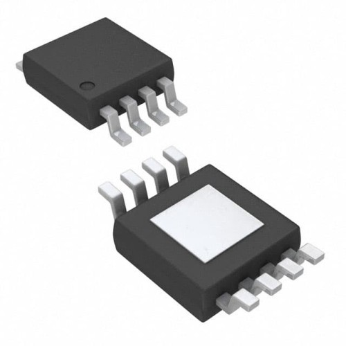

When debugging circuits using the Texas Instruments BQ24203DGN, a single-cell Li-Ion battery charger in an 8-pin MSOP package, the most common failure modes include no charging current, overheating, premature charge termination, and intermittent operation. The root causes for these issues typically fall into three categories: thermal stress from poor PCB layout, incorrect component selection for the external pass transistor and sense resistor, and counterfeit or damaged ICs. For example, a customer recently reported that their charger would start charging only to shut down after a few minutes. The root cause was a 10µH inductor with a saturation current below the 500mA charge current, causing the internal current limit to trip.
A step-by-step debugging methodology should begin with a visual inspection of the board under a microscope. Look for cold solder joints on the thermal pad of the MSOP package, as the BQ24203DGN relies on this pad for thermal dissipation. Next, measure the input voltage at pin 4 (VIN) and the battery voltage at pin 1 (BAT) with a multimeter. If VIN is present but the charger is not enabling, check the EN pin (pin 3) – it must be pulled low to enable charging. Many engineers forget to tie this pin to ground or leave it floating, which defaults to a disabled state. After verifying enable signals, use an oscilloscope to probe the ISET pin (pin 5) to observe the charge current programming voltage. A steady 1V here indicates the charge current is set to its maximum, while a lower voltage suggests the IC is in constant-voltage or pre-charge mode. If the waveform shows periodic dips, suspect a thermal shutdown cycle due to inadequate heatsinking.
Common mistakes in schematic design and PCB layout are often the culprit. The most frequent error is placing the sense resistor too far from the BAT pin. The BQ24203DGN uses a precision current sense amplifier that requires Kelvin connections to the sense resistor. Running long traces from the resistor to the IC introduces parasitic resistance that skews the charge current. Another layout mistake is failing to provide a solid thermal via array under the exposed pad. The MSOP-8 package can dissipate only about 1.5W with a proper ground plane; without vias, the IC will hit thermal regulation (around 125°C junction temperature) and reduce charge current drastically. Also, avoid routing high-frequency switching nodes (like the SW pin) near the ISET or STAT pins, as this injects noise that can cause false charge termination. In one case, a customer had a 2-inch trace from the inductor to the battery connector, which radiated enough noise to corrupt the STAT pin output, causing a phantom "charge complete" signal.
To verify component authenticity and quality, start by checking the laser markings on the top of the IC. Genuine TI BQ24203DGN parts have a specific font and alignment, with a date code that should match the reel label. Counterfeit parts often have smudged or slightly offset printing. Measure the quiescent current between VIN and GND with no battery connected; a genuine part draws less than 1µA in shutdown, while fakes may draw 10-50µA. Another test is to check the internal bandgap reference by forcing a 2.5V on the BAT pin and measuring the ISET voltage – it should be precisely 1.0V ±2%. If you suspect a counterfeit, compare the thermal pad size under a microscope: genuine TI parts have a pad that is exactly 2.0mm x 2.0mm, while some clones are slightly smaller.
For measurement techniques, use a digital multimeter for DC voltage and current checks, but an oscilloscope is essential for seeing the switching waveform at the SW pin (pin 7). The switching frequency should be approximately 1.5MHz with a clean square wave. If you see ringing or jitter, suspect poor input decoupling – place a 10µF ceramic capacitor as close as possible to the VIN pin. For current measurement, use a current probe on the battery lead rather than a shunt resistor, as the series resistance can affect the charger's sense accuracy. A thermal camera is invaluable for spotting hot spots; the BQ24203DGN should not exceed 60°C at full charge current. If the IC is hitting 85°C or more, you likely have a layout thermal issue or an external component that is dissipating too much power.
When to suspect the component versus the surrounding circuit requires a methodical approach. If the IC is not responding to enable signals and the input voltage is stable, first swap the IC with a known good part from a different reel or batch. If the problem moves with the IC, it is a component failure. However, if the issue persists with a new IC, the problem is in the external circuitry. A classic case: a customer had three boards where the charger would not start. After replacing the IC twice, they discovered a 0.1Ω resistor between the BAT pin and the battery that had been mis-specified as a 1Ω part, causing the charger to see a short circuit. Another case involved a cracked ceramic capacitor on the VIN pin, which caused the IC to oscillate and draw excessive current. In that instance, the IC was fine, but the capacitor's microcrack only appeared when the board was heated during soldering.
Real-world case studies highlight practical solutions. In one project, a portable speaker design exhibited intermittent charging when the device was moved. The root cause was a loose connection on the battery connector that caused the BAT pin voltage to momentarily drop below the recharge threshold, resetting the charge cycle. The solution was to add a 100µF electrolytic capacitor at the battery terminals to hold the voltage during brief disconnections. In another case, a customer was unable to achieve the full 500mA charge current. After checking the ISET resistor value (which was correct), they used an oscilloscope to probe the SW pin and found that the inductor was saturating during each cycle, causing the current to spike and then collapse. Replacing the inductor with one rated for 600mA saturation solved the problem. Finally, a common issue is the STAT pin (pin 6) not indicating charge status correctly. This is often due to a pull-up resistor that is too low in value (below 1kΩ), which loads the open-drain output and prevents it from going low. Using a 4.7kΩ pull-up to 3.3V resolves this.